Troubleshooting
The 9845 is a highly complex device. Although well engineered, there are quite a lot of things which can fail, either due to aging, to natural wear or to bad operation. Here are the main problem areas, separated by assembly groups:
- Mainframe RAM failures
- Mainframe ROM failures
- Mainframe LPU/PPU failures
- Mainframe electrical failures (connections, fans etc.)
- Mainframe PSU failures
- Keyboard failures
- Mass storage failures (internal tape drives, less tape media)
- Printer failures (internal thermal printer)
- CRT monitor failure
- Peripheral interface failures
- Periperal failures (mass storage, printers, plotters etc.)
Several suggestions for problem solutions are already in the tutorials, however this section is dedicated for the systematic isolation, identification and (if possible) solution of hardware related problems. Also check Jerry Walker's comprehensive documentation of his repair work on Youtube (see https://www.youtube.com/watch?v=Otvu5WNleTA).
The first part deals with common symptoms and their likely cause, the second part goes into detail for common problems of the particular assemblies. Finally there are hints where to find additional information for the repair of 9845 systems.
There are checks which you can do without any further equipment. Some checks need at least a multimeter measuring device, and some need an oszilloscope (especially for the CRTs and the PSU) or an EPROM programmer (for the system ROMs). A logic analyzer is the ultimate instrument for identifying errors in system logic via bus traces. More basic tools are a Pozidriv screwdriver, a multimeter, a logic tester and a quality low-power soldering iron with electronic solder and flux.
Cleaning of the assemblies should only be done with compressed air and isopropyl alcohol (except for the magnetic tape head which requires special magnetic head cleaner), very useful are Q-tips and lint-free fleece fabric.
This tutorial is still in a very early stage. The information which is currently provided is meant as an entry and is intended to grow, not only through my own experiences, but first of all through the suggestions and solutions of its users. So if you got a good problem description, or even better a problem solution, please send it to me and I'll include it into this section.
Please note that for everything which is related to tape media there is a special tutorial on how to save (and repair) tapes & tape drives.
Basic Rules
Here are the main rules (mainly to save your life):


NEVER OPEN THE SYSTEM WHEN THE SYSTEM IS CONNECTED TO THE POWER LINE IF YOU DO NOT KNOW EXACTLY WHAT YOU ARE DOING. EVEN NOT WHEN THE SYSTEM IS SWITCHED OFF !!!

EVEN WHEN DISCONNECTED FROM THE AC POWER SOURCE !!!
BE AWARE THE POWER SUPPLY UNIT CAPACITORS REMAIN CHARGED WITH LETHAL VOLTAGE EVEN AFTER DISCONNECTING THE AC POWER SOURCE !!!
Alright, if you are an expert and you know what you are doing, you probably also know rule number one for working with high voltages: Never work alone. In case something goes wrong, there must be someone who calls the emergency. No kidding.
Here are additional rules you should take into account:
- When you need to disassemble anything, make notes about position and orientation of disassembled parts.
- Don't hurry, work step by step and be careful not to damage anything. Spare parts are hard to get.
- Always be grounded when touching disassembled electronic parts. Use a non-static ground when laying down those parts. Although today's electronics look much more filigree, they are less sensitive against static charges than the vintage electronics. Again, spare parts are hard to get.
- If you need soldering, use a quality low-power soldering iron. Never apply heat longer than a few seconds. Use some soldering flux, it speeds up soldering operations. Too much heat will destroy signal paths and components.
Preparations
There are some things you can do to make failure isolation and identification easier:
- Remove all option ROMs from the ROM drawers
- Remove all peripheral interfaces from the backplane
- Make sure the brightness knob at the display is in the middle position
- Make sure the proper fuse is installed at the backplane
- Make sure the proper AC voltage is selected at the backplane
- Remove all expansion boards which are not necessary for operation from the left card cage (only the two rightmost boards in this cage are required)
- If the AUTOST key is locked, unlock it
- If there is an internal thermal printer installed, get some paper loaded for diagnostic printouts and for working without display (normal thermal fax paper will be OK)
Here are the information sources which are helpful in any case:
- Get a copy of the Desktop Computer Service Manual for the HP9845B/C. You can download it at hpmuseum.net (follow this link). Although it doesn't contain other solutions than to exchange complete assemblies (which today is hard to achieve, this is why it is also called 'The Board Swapper Manual'), it is one of the few printed sources for testing and failure identification.
- Also get a copy of the 9845B/C CE Handbook, also available from hpmuseum.net. Essentially, it is a summary of the information in the Desktop Computer Service Manual and some other sources, and it has a throubleshooting flowchart included.
- Finally, get a copy of the original schematics from the Documentation Section plus Tony Duell's reverse engineered Schematics of the 9845B from hpmuseum.net. Tony did an amazing work by analyzing a complete 9845B option 200 system, and the result is as good as any original schematics could be.
And this software might be helpful at least if you are able to load and run programs from mass storage:
- Get a copy of the System Exerciser for 9845B/C tapes (Rev. E ist the latest, real tapes or as image file, you can download the image here) plus TBIN binary program (included in the downloadable system exerciser image file). As already mentioned, makes sense only if your system is healthy enough to either load and run tape cartridges or to use HP-IB peripherals.
Working without CRT Display
Sometimes it may become necessary to work without display, mainly when the display is not functional. Here is a short description how the printer can be used instead for output.
When the system does a single beep at power up and subsequent boot up including the memory test is finished (it should not last longer than 60 seconds), but you still don't get anything on the screen, just type in three X's
XXX
and press the EXECUTE key. If you hear a noticeable beep, the basic logic is working.
If the CRT or the alpha control assembly is defective, but the rest of the system is OK, you can type in
PRINT ALL IS 0
now press the EXECUTE key and latch the PRT ALL key and all CRT output will go to the printer. So the system may be operated even without CRT display.
Note that the system will not boot up at all when the CRT display is removed. The cause is that the system needs a special signal generated by the CRT display in order to initialize correctly. There was a small PCB plug called "Turn-on Fixture" (HP part no. 09845-66547) which generated the appropriate signal. It was installed on the left display leg and was used by service engineers to boot up without CRT. See the Test ROM Tutorial for building a replacement for the Turn-on Fixture on your own.
Beyond this procedure, which is described in the 9845 B/C service manual on page page 2-3, there is also the possibility to remotely control a 9845 B/C from a PC, i.e. using the PC's keyboard and display instead of the 9845's keyboard and CRT, provided you got a working HP-IB interface. Again see the Test ROM Tutorial for how this can be done.
Basic Failure Identification
Before going deep, I'd recommend to do a thorough visual inspection. You should take into account that the device has been damaged or has been put together wrongly by someone who has opened the device before.
- Are there any unconnected or wrongly connected connectors?
- Are all modules at the right places/in the right order?
- Are there any loose parts around?
- Are there signs of (possibly not successful) trials of repair?
- Are there empty chip sockets?
If this all works out ok, you now may go on.
Here are some of the most common symptoms:
Symptom |
Possible Cause |
| Continuous tone when powering on | Either the monitor is defective, or not properly operating, or the connector between the monitor and the mainframe (monitor legs) is affected. |
| Beeps in intervals of approx. one second after powering on | The start-up memory test has detected an error in the system read/write memory area (block 0 and/or 1). The complete memory block is disabled and there is not enough error-free read/write memory for operation. |
| Continuous Beeps in fast sequence after powering on | Probably the LPU-to-PPU communication doesn't work (I'm not yet sure about this indicator). |
| Single beep when powering on, but freeze with message "MEMORY TEST IN PROGRESS" | Most likely ROM failure. May also be caused by RAM failures in the system RAM area or by connection problems. |
| Internal printer prints 'strange' numbers during startup, while the message "MEMORY TEST IN PROGRESS' is displayed. | RAM errors are detected during memory test. |
| Monitor is running, and the computer reacts to keyboard commands, but nothing is displayed. | A trivial cause can be that the brightness adjustment is set too dark. Another cause may be a failure in the alpha control assembly. |
| There is no reaction at all after power is applied, even the fans won't work | Most likely the fuse is blown. Much less likely there may be a defect in the power line filter. |
| Bang with smoke when powering on | Congratulations, you just killed the line filter or, even worse, the PSU. If you're lucky, only one of the capacitors is gone (best case). Contact me and I'll make you a good price for the rest of your system. See the tutorial Before First Turning On before powering the next system. |
| There is no reaction at all after power is applied, the fans do work, but neither the internal printer paper advance nor the internal tape drive light work. | Your PSU is completely defective, probably in the first stage. Check whether the drive lights of the built-in tape cartridge drives are lit. |
| There is no reaction at all after power is applied, the fans do work, as do either the internal printer paper advance or the internal tape drive light. | Your PSU is partially defective, probably in one of the voltage groups. |
| Some keys work, some don't. Or display wrong characters. | There's probably a connection problem between your keyboard assembly and the mainboard, most likely at the ribbon cable connectors. If entering a BEEP keyword results in an audible beep, the keyboard probably is ok, but the alpha control section is not. In this case, try cleaning the monitor connections (left CRT leg). |
| System freezes and CRT monitor is completely filled with patterns or garbage | Most likely ROM failure or RAM failure in the system RAM area. |
| System accepts keyboard commands and prints on printer, however the CRT monitor is filled with pattern or garbage | Most likely a defective alpha control assembly. |
These are the symptoms which can be recognized without deeper analysis. For isolating and fixing the problem, some more sophisticated diagnostics have to be performed. There are several exerciser tapes and test ROMs which can be used (if they are available), however at least one single diagnostic routine is already built into every system: the start up memory test, which is described in detail below.
The Start Up Procedure
During the start up procedure first a basic test will be performed. A single audible beep will indicate that this test was successfully completed (the 9845A does two beeps). Next, the type of CRT will be determined and the LPU and PPU will identify themselves with the help of the HALT signal (which is generated by the CRT). Note that the HALT signal is used by the 9845B/C only, the 9845A uses the DC signal instead. If no CRT is found, the system will go into a continuous loop with beeps in aprox. every second. If the LPU can't start communication with the PPU (e.g. because of bad PPU ROMs), there will be a fast sequence of short beeps instead. If the CRT could be successfully identified, the PPU starts first testing the graphics memory of the CRT (if installed), and then verifies the complete installed RAM with a RAM test. During this RAM test the 9835, 9845B and 9845C all show the message "MEMORY TEST IN PROGRESS".
If everything is OK, after 10 to 60 seconds (depending on the amount of RAM installed), on the 9845B and 9845C the message "9845 READY FOR USE" will be displayed, together with a blinking cursor. The 9845A skips the message and only shows the blinking cursor, and the 9835 displays "9835A READY FOR USE".
If a memory defect is detected, either the message "PART OF MEMORY FAILED SELF-TEST" is displayed, or the system will produce continuous beeps, or the system will just freeze. If the system is still alive, the amount of available RAM up to the first bad RAM address can be retrieved with the LIST statement.
This type of error reporting is not too useful, but there is actually a more verbose feature:
If you have a working internal thermal printer installed and it is loaded with paper, the memory test which is performed during startup will - if it fails - prints out some basic information about the location of detected memory defects. You can test the principle operation of the printer by just pushing the PAPER ADVANCE key. If the printer has valid power, it should advance the paper one line.
How the printout is to be interpreted is shown with the following example:
00004 170000 125250
All numbers have octal notation. The first number is the memory block where the error occurred (the block number shows only two digits on the 9835A/B printer), the second number is the address, where the error was detected plus 100000 (octal), and the last number is the 16-bit-pattern which was read. So this example says: RAM test failed in memory block 4 at address 070000 with the memory content 125250.
In order to get a better idea on how the error message should be interpreted, it is helpful to know how the start-up memory test works:
- First, the 16k words of the PPU RAM block 1 are tested with a pattern test. This test is a full block test, i.e. if an error occurs during this test, the affected block, address and content are output and any further PPU RAM block test is aborted (this is the reason why there is never more than one error reported in the PPU memory block 1).
- Next, after the PPU RAM block is cleared with zeros, the LPU memory blocks are tested. Since only even block numbers (0, 2, 4, ...) belong to the LPU, this test is performed only on even block numbers.
The LPU RAM test differs from the PPU RAM test in that the actually installed amount of RAM varies from system to system. So before testing memory, the system has to determine at which addresses memory is installed, and at which addresses not. The address space for each LPU memory block reaches from 0 to 32k (so two complete memory blocks fit into the full 64k address space of the LPU). Now the system divides the whole memory block into 8 pages of 4k each. Starting with the highest page and going down to the lowest page, for each page a write/read quick-check is performed only on the first word of the page. The result is either memory installed, memory absent or error.
If a page quick-check results in memory absent or error, the memory of the checked page and all memory below is assumed as unusable and no further checks for the lower pages are performed. This shows the purpose of the start-up memory test, it is obviously not intended for identifying bad RAMs, but rather to identify the usable continuous RAM space for each memory block.
The usable memory will then be tested with the same pattern test as is was performed on the PPU RAM, however, in case a RAM defect is found, this pattern test skips the rest of the 4k word page and continues with the next higher 4k word page (again first bottom-up until either the upper block limit is reached or an error is found, than top-down in the same manner) until the whole 32k memory block is tested. Since there is never more than one error reported within a 4k page, the LPU RAM test is a bit more granular than the PPU RAM test, where no more than one error is reported for 16k.
The PPU RAM test runs from octal address 140000 up to octal address 177775 within memory block 1, the LPU RAM test runs from octal address 100000 up to octal address 177777 within all even memory block numbers starting at block 0, as far as RAM is installed. Since the address space for the 9845 is limited to 64 blocks total, the highest possible even block number tested will be octal 76.
The memory scan starts at octal 100000 and not at 000000 because the tested memory block is mapped into the upper memory address space, which starts at octal 100000. The lower half of the tested blocks is from octal address 100000 - 137777, the upper half of the tested blocks is from octal 140000 - 177777. For the identification of defective RAM chips it is only relevant whether the error happened in the lower half (i.e. below 140000) or in the upper half of the tested block (it shows which row of RAM chips is affected).
Here is how the pattern test is done:
First the tested memory aera is filled with octal 125252 (= 10101010 10101010).
Second, the block is tested bottom up:
- Read content from current address and keep that result in mind
- Write octal 052525 (= 01010101 01010101) at current address
- Read again content from currrent address
- If second result is not 052525 or sum with previous read is not 177777, output an error with block, address and content, and abort
- Otherweise repeat with incremented address until the whole memory area is tested.
When the complete block is tested OK, it is tested again top-down with inverse pattern:
- Read content from current address and keep that result in mind
- Write octal 125252 (= 10101010 10101010) at current address
- Read content from current address
- If second result is not 125252 or sum with previous read is not 177777, output an error with block, address and content, and abort
- Otherweise repeat with decremented address until the whole memory area is tested.
Finally, a special memory info area at the upper end of each memory block, the block descriptor, is updated.
As you can see, there is a cross check with two inverse patterns which is a good method for finding RAM errors fast, however there are several points which make it difficult to use the error messages for a reliable fault detection:
- The PPU RAM is tested in a way that only one single error (the first which is encountered) will be reported, the rest of the PPU RAM block will not be tested.
- Not the read content which caused the failure is output in the error report, but the same RAM address is read again and this data is printed. So it happens that the printed bit pattern differs from the data which originally caused the error (i.e. for intermittent failures), and it cannot always be used for a definite identification of the bad RAM chip.
- It is not reported, whether the 125252 or the 052525 pattern was expected, so we have to guess which test pattern produced the erratic memory content.
- If we see the 052525 pattern as result of a failed RAM read, we just now where the failure happened, but nothing about the failed bits (since there is a compare against the previous fill operation, which already might have failed).
- Due to the odd implementation of the LPU RAM identification, errors during the quick-test prevent any pattern testing of the LPU RAM pages below the bad RAM address.
A workaround can be to repeat the boot several times and to compare the results in order to get more reliable information. Sometimes there are several similar errors in sequence, which reflect a pattern of defects which can suggest a defective RAM chip or address line.
Here is a typical example of a start-up print:
000004 100112 052525
000004 110112 052525
000004 120112 052525
000004 130112 052525
The example suggests that there is a bad chip in the lower half of the fourth memory block (neither the fact that the error happens at the (octal) 112th word of each 4k page nor the content 052525 are really useful).
However, it can happen (sometimes after repeated system boots) that the reported content (the last column) is neither 125252 nor 052525, and then you in fact got a hint which memory chip is bad. You then can check which of the the three values 177777, 125252 or 052525 is nearest to the listed value. With a bitwise compare you then can identify the faulty bit(s) and with this the bad DRAM device(s) (see the appropriate service manuals to locate them on their PCBs). But, as I said, due to a somewhat strange detail in implementation most of the start up diagnostics will print the test pattern rather than the result which is returned from the memory read. And even after fixing this, there may still be faulty chips which are reported but can't be located.
A commented disassembly of the startup memory test procedure can be downloaded here.
As a conclusion, the test is not the big thing, however for many systems it will be the only one which is available, simply because it is built into every system firmware. A better implementation of a memory test is found on the 9845 System Exerciser tapes. Unfortunately this doesn't help for troubleshooting boot-up problems (you won't get far enough to launch a program from tape). So HP's service personal had a special Test ROM module, which could be plugged in just as an option ROM and replaced to system ROM for diagnostic purposes. Among other useful diagnostic utilities, the ROM included a RAM test usable for the identification of bad RAM chips.
In-depth Failure Analysis
The built-in diagnostics in general provide just hints for what is going wrong, without giving the information which is necessary to isolate the problem so that it can be fixed. There are several standard ways HP already had included in its support and repair procedures, namely the use of diagnostic programs and hardware analysis with logic analyzers.
Which of the diagnostics to use depends primarily on the operational state of the system.
If the BASIC language system is fully functional, the 9845 B/C Exerciser tape provides to most comprehensive tests for nearly everything, including a large number of peripheral devices. The 9845 Test Binary program is also a good choice to use, because it contains many tests for internal components, but is not as comprehensive as the Exerciser suite, and lacks periperal tests. The Test Binary program, however, can be loaded both from BASIC and from the Test ROM, and therefore may be used even if the BASIC language subsystem fails.
If the system does not boot up because of ROM failures or read/write memory errors, but all other core components (PSU, processors, main board) work, the 9845 Test ROM is the way to go. There is even a way to remotely control the 9845 in case CRT and/or keyboard fail.
If both the Test Binary and the Test ROM can't be used because the core components fail, the PSU has to be checked (oscilloscope, volt meter etc.), and/or the core logic operation (e.g. bus signals) has to be analyzed (logic analyzer).
For using the 9845 B/C Exerciser, refer to the Desktop Computer Service Manual for the HP9845B/C.
For using Test ROM and Test Binary, see the Test ROM & Test Binary Tutorial.
For using a logic analyzer with the HP 9845, please refer to the Using a Logic Analyzer Tutorial. Note that a deeper understanding of the 9845 processor and bus operation is required for troubleshooting with a logic analyzer, which again assumes you are familiar with the low level operation which is best described in the 9845 patent documentation, in combination with the 9845 schematics. Both can be found in the Document Section. Also take a glance at the System Architecture Section as primer.
Most Common Failures by Assembly
To be continued...
Repair Resources
To be continued...
Screen Mold
The 98750A standard monochrome monitor is frequently affected by something looking like "mold spots", especially at the border of the screen. The spots look unattractive, but generally don't have an influence on the use of the system. The change is caused by the adhesive which was used to fixate a face-plate in front of the CRT surface with dual purpose, acting both as an additional protection in case of implosion and as anti-glare screen layer. Under certain conditions (presumably certain combination of temperature and humidity) the adhesive seems to disintegrate at the outer screen regions. The 98770A color display and 98780A enhanced monochrome monitor seem not be be affected.

Screen "Mold" on 98750A Monitor
It is reported that this can be fixed by opening the display casing, getting the CRT tube out of the box, separating the face-plate from the CRT (e.g. with a thin wire such as a piano string), cleaning both and rebonding the screen with new adhesive (see here for the procedure).
Probably an even better way for separating the face-plate from the CRT surface is to heat up the front of the CRT to 60-80 degree centigrade, so that the goo gets chewy, and then use a knife with flexible blade to separate the face-plate from the CRT surface. However, I'd not recommend removing the plate anyway, because it is mostly a cosmetical problem and you may damage either the screen or yourself.
I did it just for exercise with an already broken tube. Here are the results:
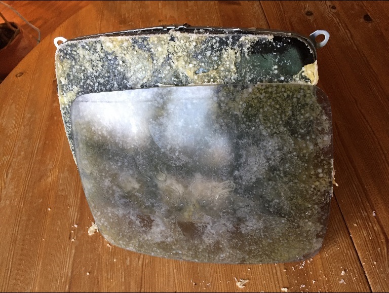
Face Plate Separated from CRT
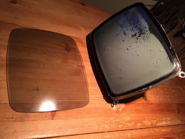
Separated & Cleaned
A positive side effect is that without the goo, the display gains intensity (looks significantly brighter). Whether you re-mount the face plate or not is mainly a matter of taste (remember it also works as anti-glare surface).
In any case, be extremely careful when handling the CRT tube, especially with the neck of the CRT which can easily break off (you may use a bucket to keep the tube in the right position), and wear eye protection glasses and some protective clothes all the time! The CRT may still hold high voltage even hours after the last operation, and may be subject to implosion if handled in the wrong way.