The 9845C
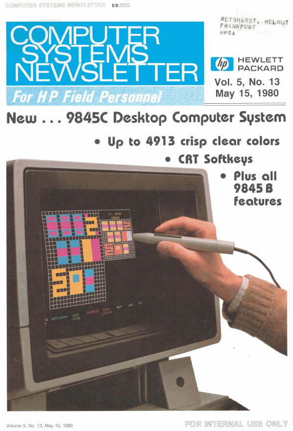
![]() The 9845C, first mentioned in the sales brochure from January 1980, introduced in the December 1980 issue of the HP Journal and with first appearance in the HP Catalog from 1981, was the top-of-the-line model of the 9845 series, and it was the very first HP computer supporting color. Simply said, the 9845C brought color into the 9845 series.
The 9845C, first mentioned in the sales brochure from January 1980, introduced in the December 1980 issue of the HP Journal and with first appearance in the HP Catalog from 1981, was the top-of-the-line model of the 9845 series, and it was the very first HP computer supporting color. Simply said, the 9845C brought color into the 9845 series.
Like with the whole 9845 design, HP's engineers did a rather complete job. They not only added a precise color display, but also soft-keys and a light pen for ergonomic software design. And it utilized a full size color frame buffer with hardware accelerated line drawing and fill operations. Maybe the design was a bit too complete, because the overall complexity reached a degree which was not only expensive, but also minimizes the probability to discover a fully operating 9845C today.
But never mind, despite of - or better just because - of its complexity, the 9845C really had everything a workstation needs. It provided a high-power 16-bit dual-processor system with at least 128 KBytes firmware in ROM, up to 1.5 MByte RAM, integrated tape mass storage, full-size keyboard with numeric keypad and function keys, full-width fast and quiet thermo printer, a wide range of peripherals, connectivity to mainframes as well as to other workstations, and a clear, hardware accelerated graphics display with up to 4,913 colors.
The 9845C was designed for best-possible compatibility to the 9845B, in fact, the 9845C was basically a 9845T with revised graphics firmware, color coded special function keys and a color display. And it was the 98770A color display which made the difference. It included a separate power supply, a vector generator based on the AMD2900 bit-slice architecture, graphics memory with three planes of 32 KBytes each, a connection interface to the mainframe, and a light-pen logic. The display front showed eight soft keys on the lower end of the screen, and 39 (!) alignment controllers behind a door which could be used to fine-tune the color convergence of the display.
Without doubt, the color display was the faster computer than the 9845 mainframe itself. And it drew even more power from the line, the combined input power consumption of mainframe and power display could reach almost 1,000 Watts.
Obviously, the bit-slice processor design of the color display inspired the 9845 system designers to perform later another step and replace the old hybrid language processor completely by a AMD2900 bit slice system, known as the 9845 model 200. For certain calculations, this accelerated computation by a factor of 7, which made the 9845 even more performant.
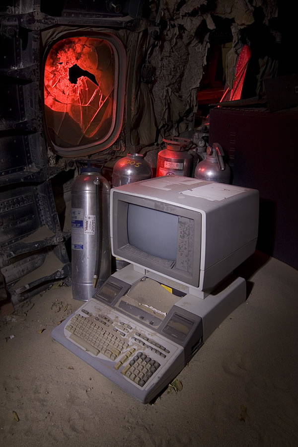
9845C, Courtesy of Troy Paiva |
Have a look at this 9845C model, a photograph by Troy Paiva from his 'Lost America' series within a cool environment. Troy found the HP 9845 when he was shooting the aircraft boneyard called Aviation Warehouse at El Mirage Dry Lake. One section of the yard is used for storage. The owner takes the upper halfes of airliner fuselages and uses them as shelters for all kinds of equipment and parts. See this link for a flicker diskussion on this item, or this site for more from the Lost America series of photographs. |
9845C Computer Graphics Innovations
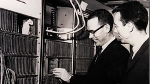
Ivan Sutherland and
Dave Evans 1969 with LDS-1
Vector (or analog) displays had been available for a quite long time and represented state of the art for computer graphics for (almost) any purpose. Line generation was more or less the task of the CRT in combination with some digital circuit which worked display lists containing only the end points for each line plus - depending on the system - intensity, feature (like blinking) or depth (Z-value) information. In fact vector displays had been quite similar to CRT plotters. Most digital processor work focused on calculating the endpoints including matrix transformations for coordinate scaling & 3D transformations. Normally a vector display was combined with such a coordinate processor and a minicomputer controlling the overall action (like usage within CAD programs).
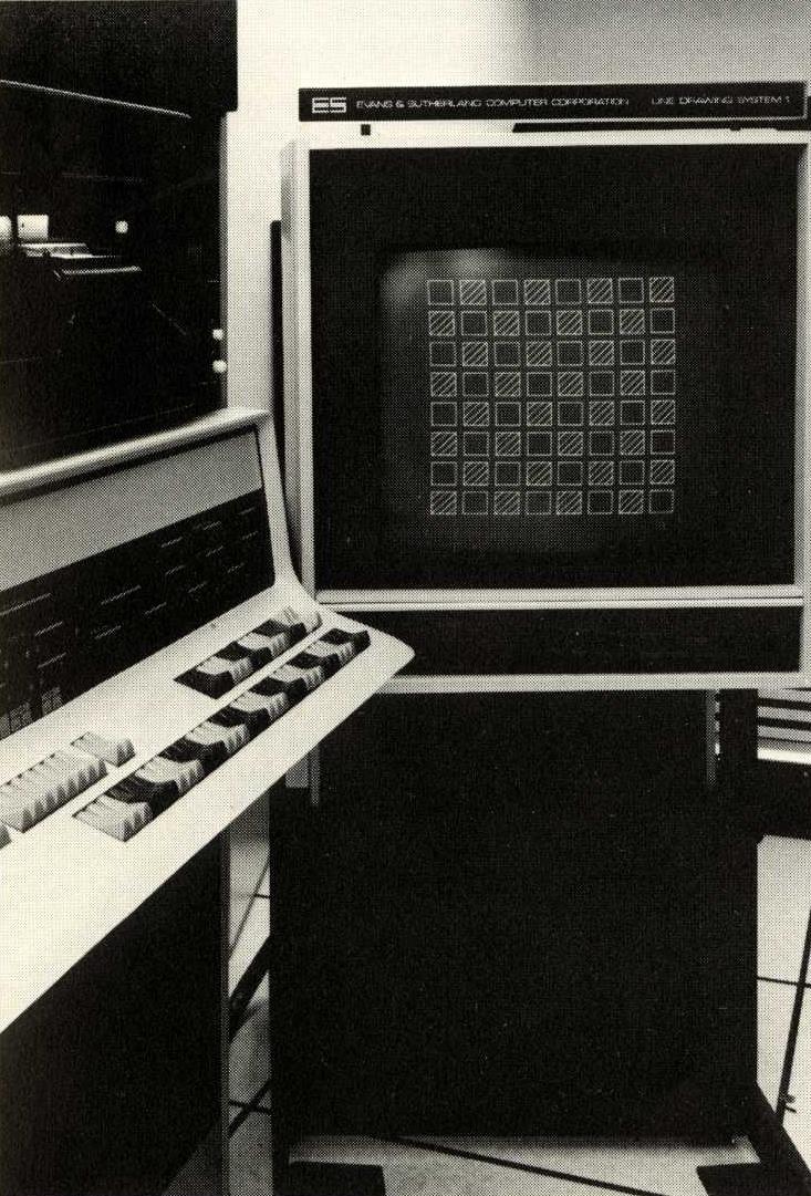
Checkerboard on LDS-1
However, frame buffer displays as - again - commercially introduced by Evans & Sutherland in 1973/74 required lots of RAM, and memory had been extremely expensive at the time. The Evans & Sutherland Picture System in 1974 already offerend 512 x 512 pixels with 8 bit grayscale for $15,000.
In 1976, Cromemco released a low-cost frame buffer based video add-on for the MITS Altair "personal" computer. This very first graphics solution for a microcomputer was called "Dazzler", and consisted of two boards, which plugged into the S-100 bus of the Altair. It was capable producing a composite video output with 64 x 64 "pixels" with 16 fixed colors in color mode or 16 intensities in black and white mode, or 128 x 128 bilevel pixels with one selectable color. The 2 kByte frame buffer actually was located in the main memory and accessed via direct memory access (DMA).
Vector Graphic's High Resolution Graphics board one year later doubled that resolution to bi-level 256 x 240 or 128 x 128 with 16 shades of grey, but no color. It used a dedicated 4K static RAM board for its frame buffer. A similar board came from Matrox in 1978. The later Super Dazzler Interface (SDI) was even more advanced in that in 1979 it implemented a dual color resolution of 756 x 484, or 378 x 241 with 16 colors (out of 4096 via look-up table), utilizing multiple dual-ported 48K frame buffer RAM boards and real-time display control for windows and mixed resolutions.
Two years before the 9845C, Hewlett Packard already offered a high resolution frame buffer monochrome graphics option for the HP 9845A. In 1980, HP implemented color in the 9845C simply by combining three frame buffer planes to a frame buffer with three bits per pixel, thus providing eight different colors. Although today 24 bit frame buffers are common, the frame buffer principle still is the same.
In a frame buffer, all graphics information is produced by writing into the frame buffer memory. For the HP 9845A this was done by the PPU processor, however compared to common vector displays, line drawing suffered from a serious degrade in drawing speed - each pixel had to be calculated by the CPU and transferred via a 16-bit I/O operation into frame buffer memory.
In contrast to the 9845A, the 9845C was intended (among other purposes) for CAD applications, and engineers who used to work with vector displays before would not have been happy with a slow frame buffer system. So HP's engineers added acceleration for vector drawing & area fill in hardware, resulting in a speed of up to 5,000 vectors per second. This had been another great innovation at the time, and HP chose a quite unusual way how to do it - they used a bit slice processor design for this, so the specialized graphics primitives could be 'microcoded' for achieving highest performance results. Probably the first GPU available for frame buffer graphics.
The only drawback was that refreshing the video display from the frame buffer and vector generation could not be performed simultaneously, since frame buffer memory access had to be done exclusively (dual port memory or double buffering probably had been out of budget scope). Hence, vector generation - although running at full memory speed with up to 2 million pixels per second (!) - was restricted to the CRT horizontal & vertical retrace cycles (about 23-45% of the display timing).
Another great innovation with respect to computer graphics had been the high level graphics programming system, which not only provided a high level of abstraction, but also included capabable 3D libraries with fast matrix operations and a unified model for user interaction (including light pen control and menu techniques) and graphics output for a large number of graphics devices.
In fact, it seems that the HP 9845C had been the very first system, which implemented both high-resolution color frame buffer and hardware accelerated line generation & area fill into one system. Starting with the HP 9845C, high resolution frame buffer graphics became one of the primary characteristics of workstations in general.
The Color Principle
The 9845C used three planes of one bit per pixel each. Each graphics pixel was composed by three bits, one from each plane, which then were converted into eight primary colors (black, red, green, blue, magenta, cyan, yellow and white).
The mapping between memory planes and colors could be changed through the so-called "musical memory", a 9-bit wide register (3 bits for each plane), which assigned one of the 8 colors to each plane. The values were switched by the bits in the memory planes and or'ed together for the final color. The register could be programmed in BASIC with the MEMORY instruction. By default the assignment was RED for the first plane, GREEN for the second and BLUE for the third plane, so that all 8 colors could be produced according to the following scheme:
| Color | Red Plane | Green Plane | Blue Plane |
| BLACK | 0 | 0 | 0 |
| MAGENTA | 1 | 0 | 1 |
| RED | 1 | 0 | 0 |
| YELLOW | 1 | 1 | 0 |
| GREEN | 0 | 1 | 0 |
| CYAN | 0 | 1 | 1 |
| BLUE | 0 | 0 | 1 |
| WHITE | 1 | 1 | 1 |
For changing the color mapping, just the musical memory register had to be changed (the memory planes did not have to be rewritten). Unfortunately, the HP engineers missed the final step creating a real 8-entry look-up table with intermediate colors, so whatever mapping you define, no other than the 8 primary colors can be produced. With a real palette table, even image processing would have been possible.
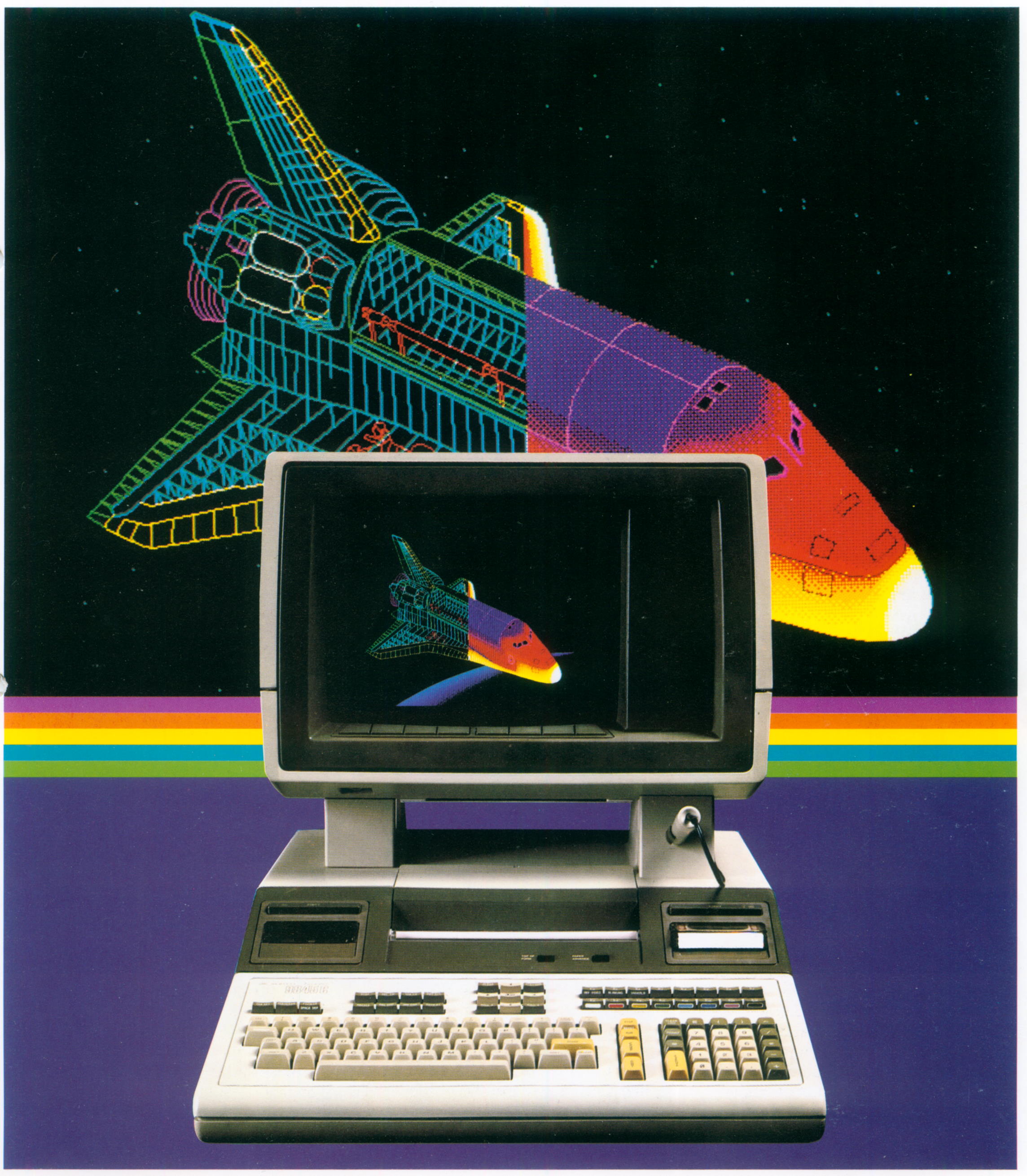
All line drawing and fill operations were specified with color information either as a HSL triple (hue, saturation, luminosity), or as a RGB triple (red, green, blue intensity). Actually, lines could only produced with one of the 8 primary colors, but for fill operations the color shades were generated by a simple cell dithering algorithm with a dominant and a non-dominant color in a 4x4 pixel cell. Since in a 16 dot cell there are 17 dithering patterns with different average intensity, up to 17² = 4,913 eye-averaged color shades were possible. This technique saved expensive graphics memory and was perfect for technical applications like CAD, however somewhat impractical for image processing (there was no scanner peripheral device anyway, although it was good practice to modify a plotter into a scanning device).
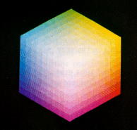
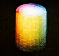
RGB Color Cube and HSL Color Cylinder
Both line drawing and polygon fill operations were hardware accelerated, there was a special vector generator for that purpose, which worked independent of the mainframe's processing units.
As a result of the engineering efforts, definition, sharpness and saturation of color were of outstanding quality. The 9845C system had been the favorite source for scientific imaging at the time. Looking to the IBM PC, a comparable system was available with the EGA graphics in 1984, which was four years later.
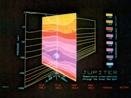
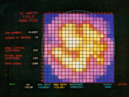
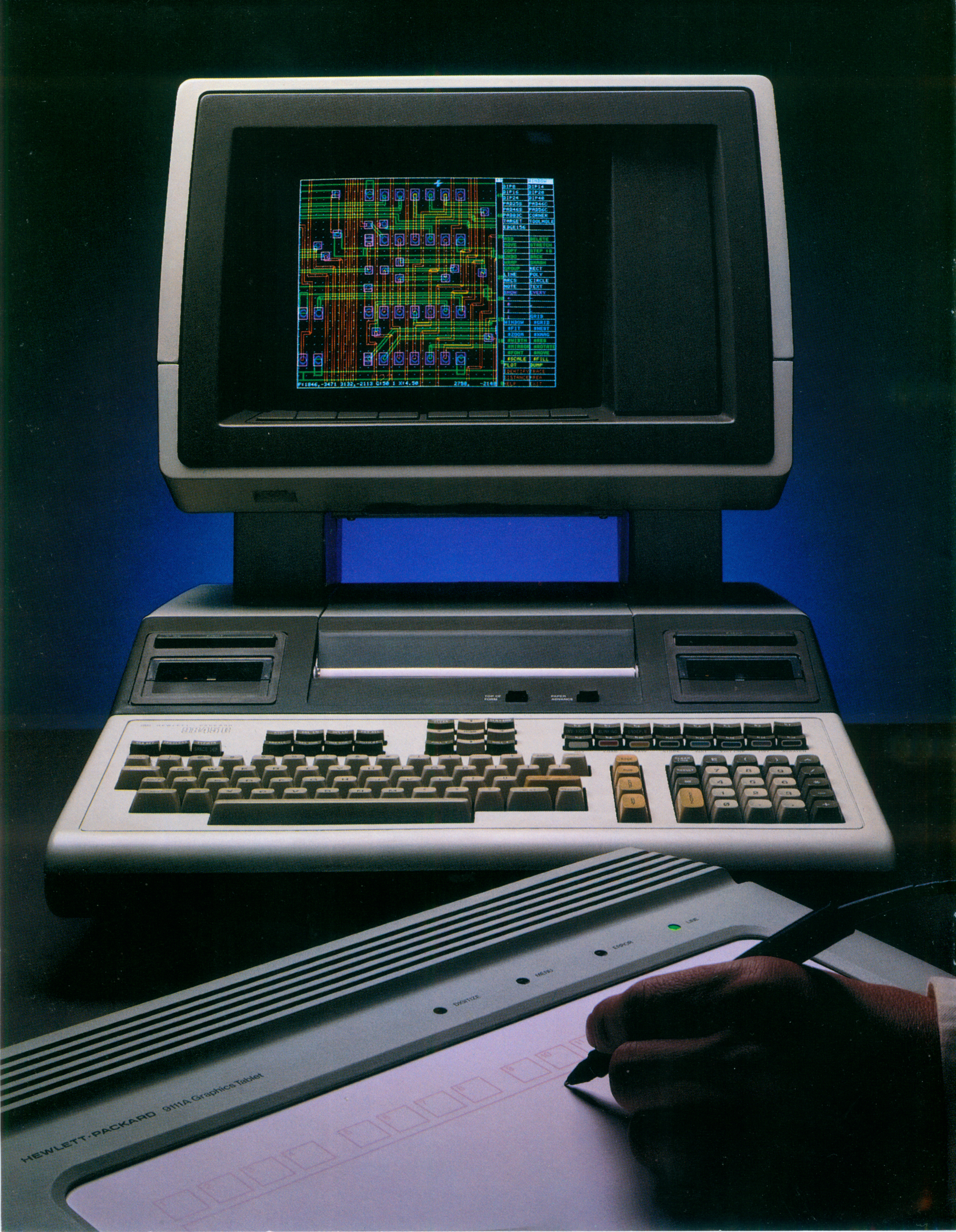
Sample Screen Shots (Jupiter Red Spot and Die Production Yield)
The colors could be directly accessed in BASIC via the special function keys k8 to k15, which were color coded. The desired color could be activated by pressing the CONTROL key simultaneously with the appropriate special function key. Apart from the logo, the color coded keys are the only visible difference between the 9845B and the 9845C mainframe.
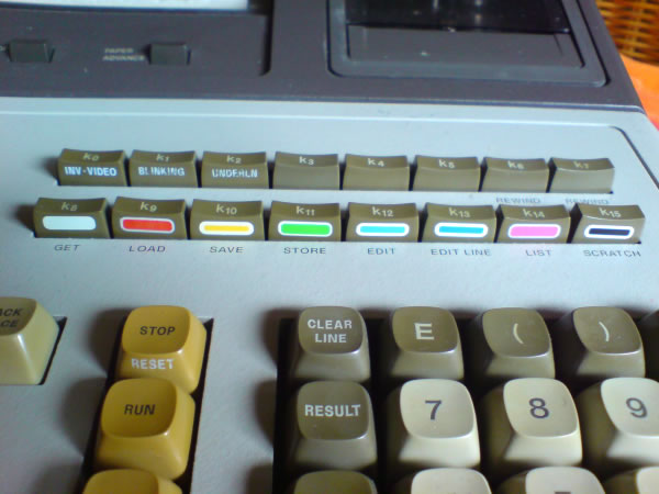
Color Coded Special Function Keys on the 9845C
The same effect can be achieved by using the character codes (decimal) 136 to 143 within PRINT statements (e.g. PRINT CHR$(137);"HELLO" prints the word "HELLO" in red), or alternatively by using the escape sequence ESC+"&d" with one of the characters 'H' to 'O':
| Color | Character Code | Escape Code |
| WHITE | 136 | ESC+"&dH" |
| RED | 137 | ESC+"&dI" |
| YELLOW | 138 | ESC+"&dJ" |
| GREEN | 139 | ESC+"&dK" |
| CYAN | 140 | ESC+"&dL" |
| BLUE | 141 | ESC+"&dM" |
| MAGENTA | 142 | ESC+"&dN" |
| BLACK | 143 | ESC+"&dO" |
It is not possible to mix different colors for foreground and background of characters.
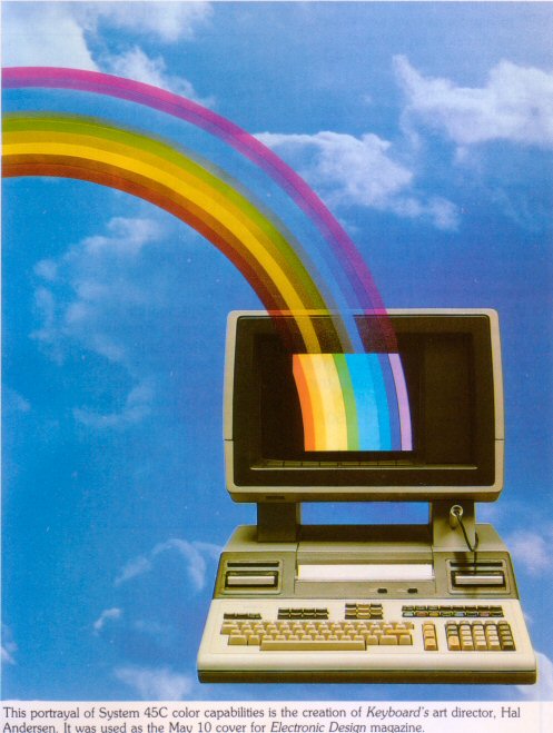
There was a special unit avaliable, which could be used to mount a camera in front of the CRT in order to produce high-quality screen shots. As already mentioned above, in the early 80's, the 9845C was a quite popular source for technical and scientific illustrations. You can identify those illustrations either through the dithering scheme or through the unique HP screen character font. And if you ever saw the 1983 "War Games" movie, all those large-scale NORAD monitors were fed with computer graphics generated by a 9845C.
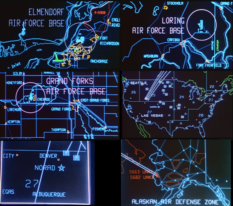
Some Screenshots from the original War Games movie, produced with a 9845C
See the Screen Art section for more details (especially the 9845C demo is a 'must-see').
Pointer Types and Human Interaction
One of the success factors was that HP asked their customers before they moved to the drawing board. The 9845C is an early example, how human interaction and ergonomy was implemented in that time. Graphical user interfaces with eye-hand coordination were still in the research phase, however the 9845C already implemented principles like softkeys for screen menues, screen pointing with light-pen and hand-move control with graphics tablets.

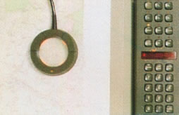

Standard Pointer Devices (Light-Pen, Digitizer, Graphics Tablet)
See the Mouse Project Section for learning how to add mouse support for any 9845 system on your own.
Soft-Key Menu
The HPGL subsystem was independent of the actual graphics hardware. So any pointing device could be connected and used in a very similar way. And graphics output could be directed to any HPGL device, including CRT screen, plotter and printer. If mouse or joystick control for the 9845 would be desired, only a suitable driver has to be developed. This unified approach was light-years ahead of the later IBM PC solutions.
In addition to the pointer devices, the 9845C introduced a user-friendly menu system, based on eight soft-keys built into the monitor and software controlled soft-key labels on the bottom lines of the screen. For this purpose, the original 25 lines were extended to 28 lines (the original 25 lines plus one separating line and two label lines).
Graphics Firmware
The 9845C requires a pair of special PPU system ROMs and a color or enhanced graphics option ROM. The system ROMs which are 9845C specific are the ROMs which cover the address range of octal 000000-017777 (position CE1-LB and CE1-UB on the PPU RAM/ROM assembly). They have the Part No. 1818-1208 and 1818-1209 for the standard configuration and 1818-1591 and 1818-1592 for the use with 512 KByte RAM expansion boards.
The required option ROM is either a 98770-65501 Color Graphics ROM or a 98780-65501 Enhanced Graphics ROM (the latter works also with a fast monochrome display). Both option ROMs extend the basic graphics instruction set of the 09845-66517 standard Graphics ROM by 35 additional graphics commands.
Some new commands are:
ALPHA, AREA COLOR, AREA INTENSITY, CONVERGE, DEGAUSS, EXIT ALPHA, GRAPHICS INPUT IS, GRAPHICS INPUT ... IS ON, GRAPHICS INPUT ... IS OFF, GSTAT, KEY LABELS, LABEL KEY #, LABEL KEYS, LAXES, LGRID, MAT AIPLOT, MAT APLOT, MAT ARPLOT, MAT IPLOT, MAT PLOT, MAT RPLOT, MAT SYMBOL, MEMORY, ON GKEY, OFF GKEY, POLYGON, RECTANGLE, TRACK ... IS ON, TRACK ... IS OFF
Completely new are
- all commands for specifiying color,
- for graphics input,
- for using softkeys, and
- for drawing polygons and rectangles.
And the new ROM provides support for the fast BASIC processing of object lists via matrix operations (useful for the fast vector generator).
The 98780-65501 Enhanced Graphics ROM adds support for the fast monochrome CRT display plus rubber banding, fast tracking and fast alpha. If used in a 9845C, fast erasing, arcs and circles and rubber banding with no background loss won't work. However rubber banding on a 9845C may be emulated in software with the RUBBND binary program which is included with the System 45C Utilities package. Programs STORE'd with one ROM can be run with the other with some minor exceptions.
All firmware changes are documented in the HP 9845 BASIC Programming Manual of September 1981 (see the reference tables in the appendix).
from: hpmuseum.net
Technical Specifications
|
|
Close Up
 |
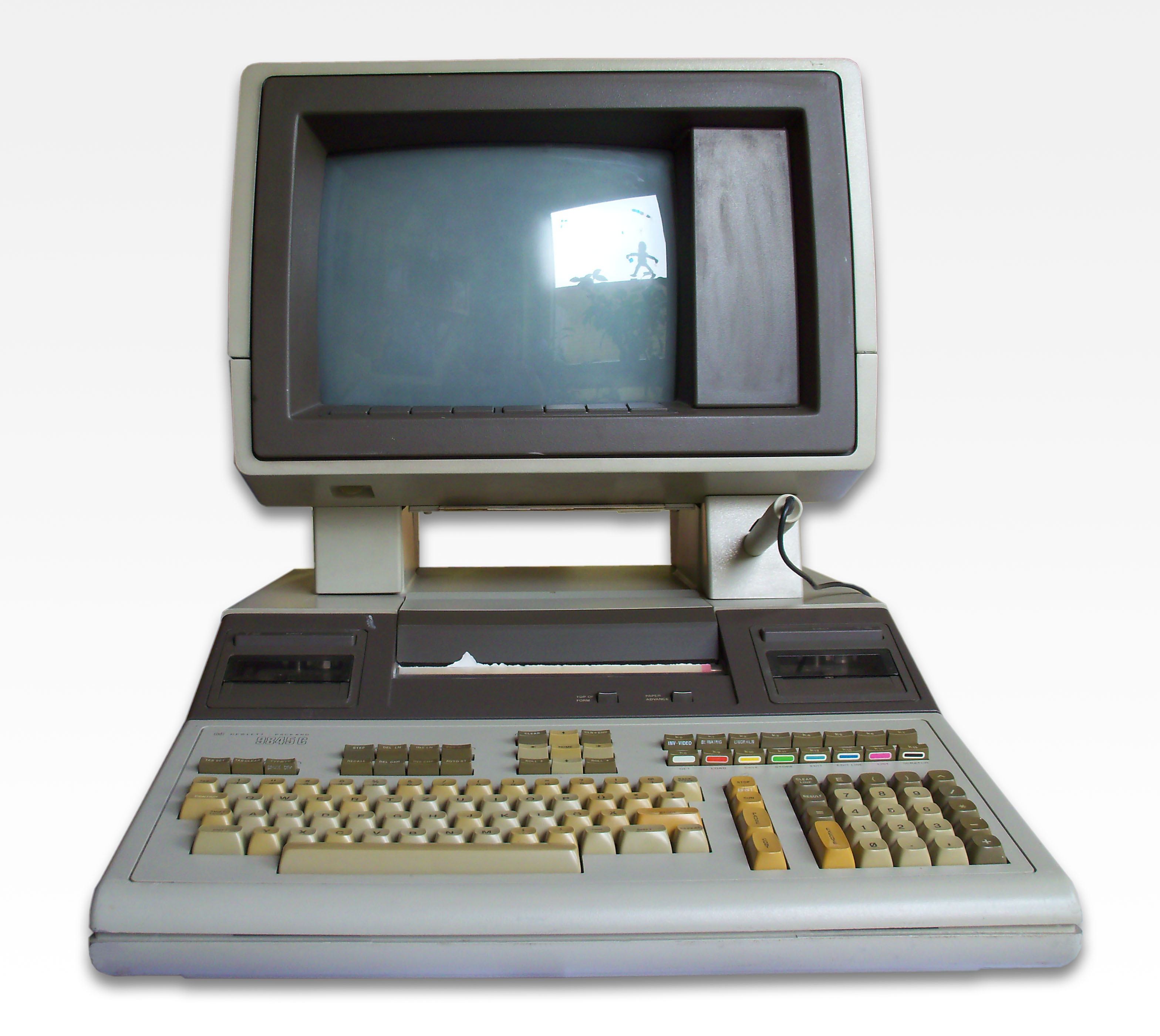
Appearance of the 9845C is quite similar to a 9845B Model 200. Mainframe and display all look the same, and in fact most of the mainframe is the same as for a 9845B. The difference is inside the display, which has nothing in common with the 9845B but just the shell and the dimensions. |
 |
View from the left hand side. See here the light pen attached. |
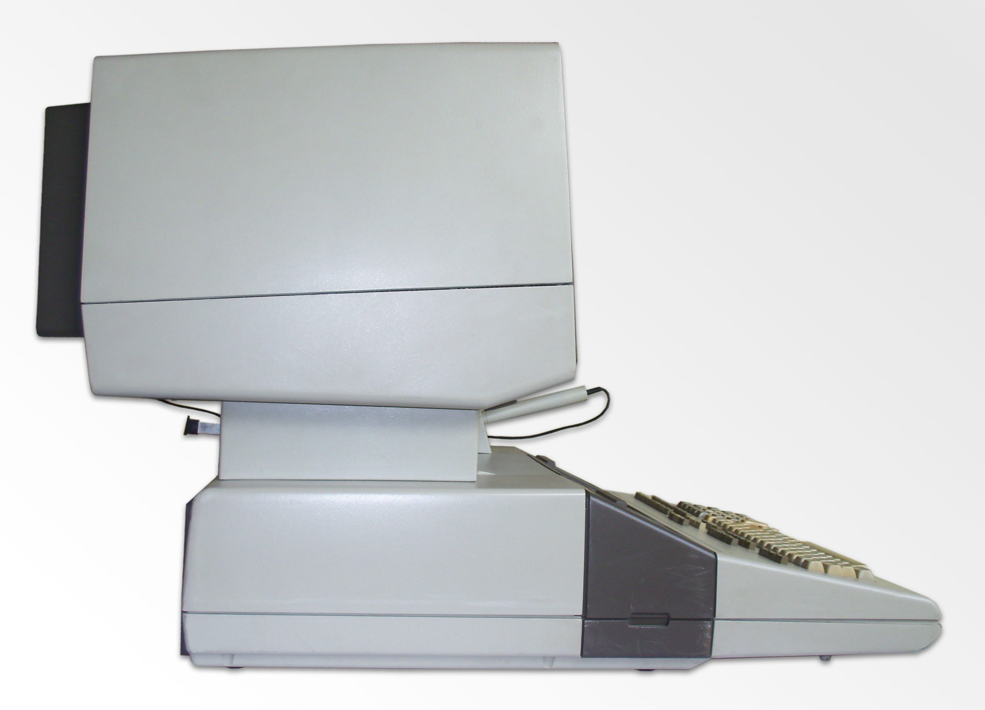 |
In the side view the proportions get evident, the display takes much of the space and weight of the complete system. Due to its 30 kg, it was strongly recommended by HP not to lift and carry the display by just one person. |
 |
The display with its 13 inch diameter appears significantly larger than that of the standard 9845B. On the right side of the CRT a panel hides the controls for convergence calibration. |
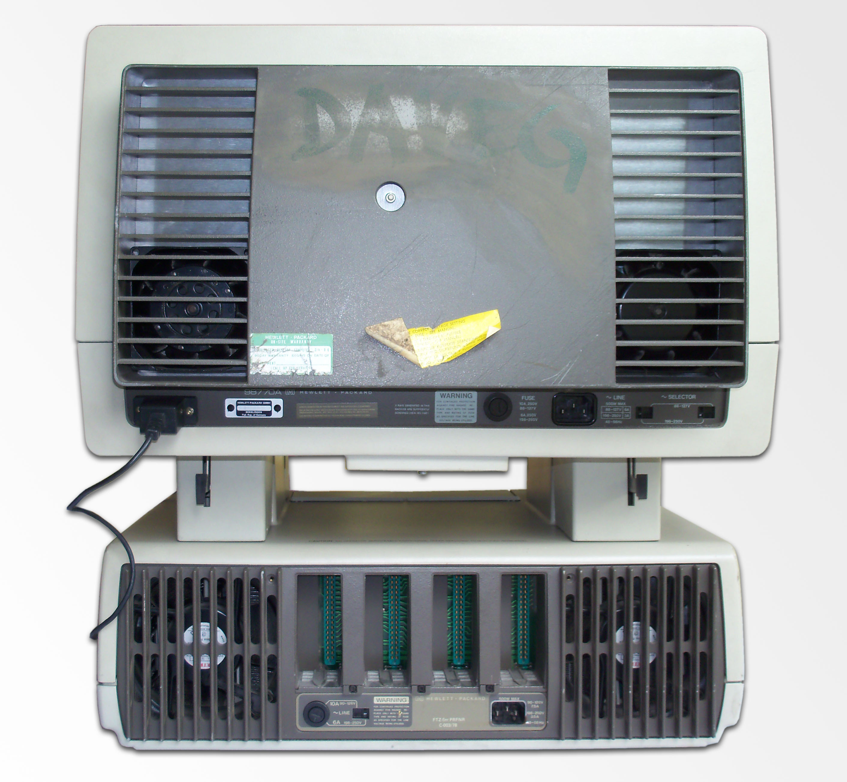 |
The back of the system again looks very much like the 9845B Model 200. On the left there is the connector for the light pen. The 9845C displayhas its own power supply and therefore needs its own power cord. Due to the power consumption, the 9845C display also needs its own fans. |
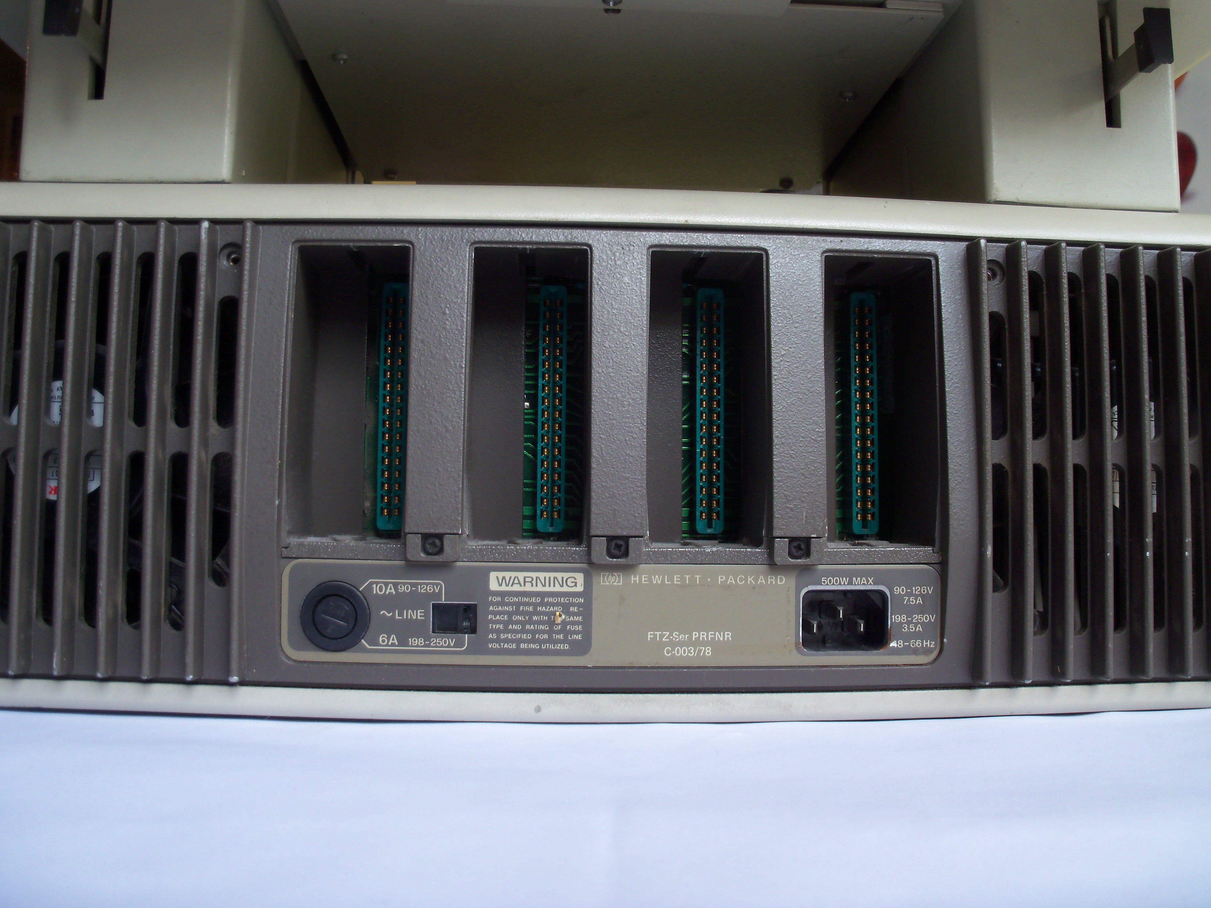 |
Just as all other 9845 models, the 9845C has four I/O ports for plugging in peripheral interfaces. |
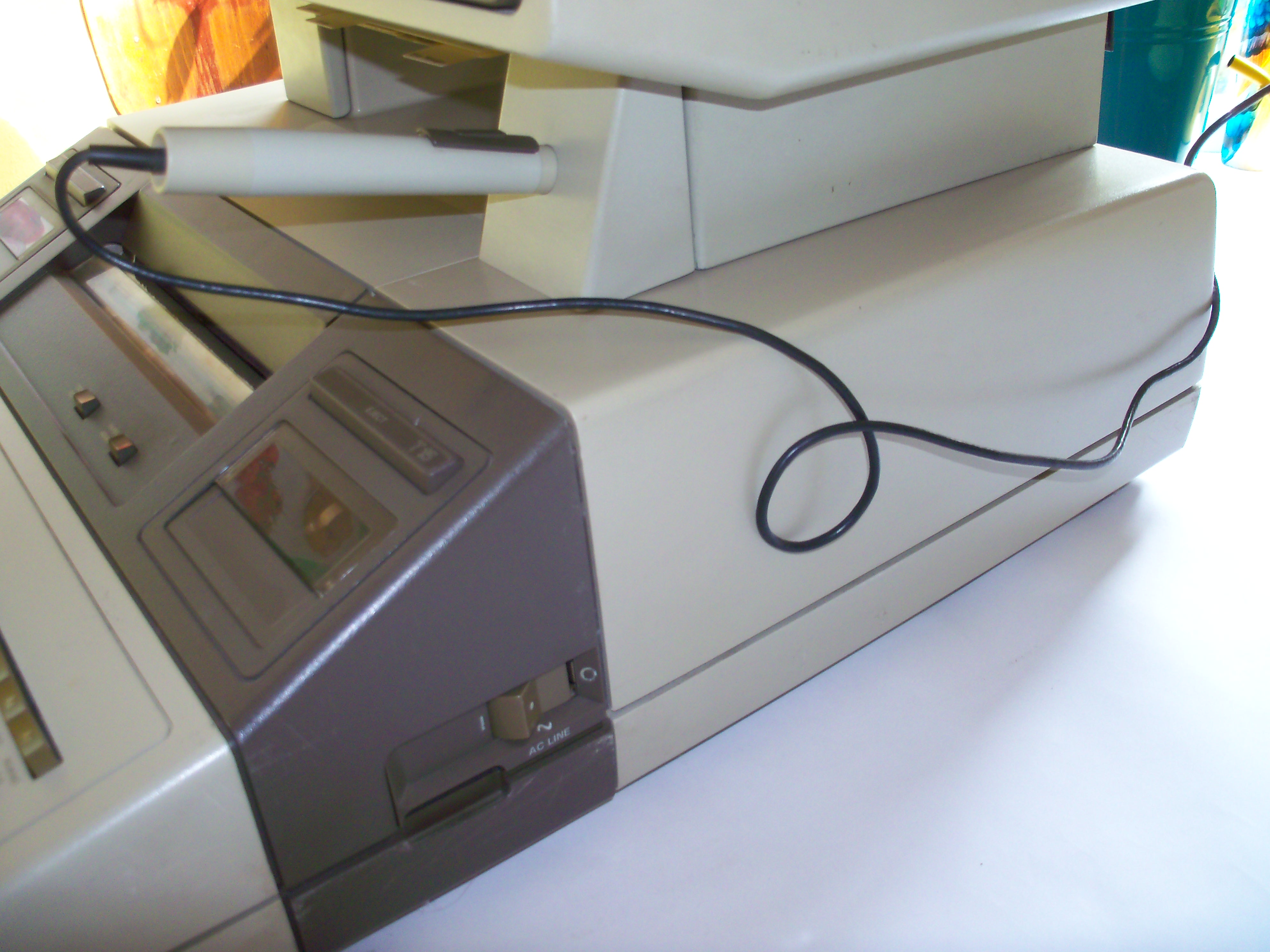 |
The light pen was part of the 9845C concept. Here it can be seen in its parked position. A special bracket could be installed on any of the display legs (suitable for left and right-handed users). |
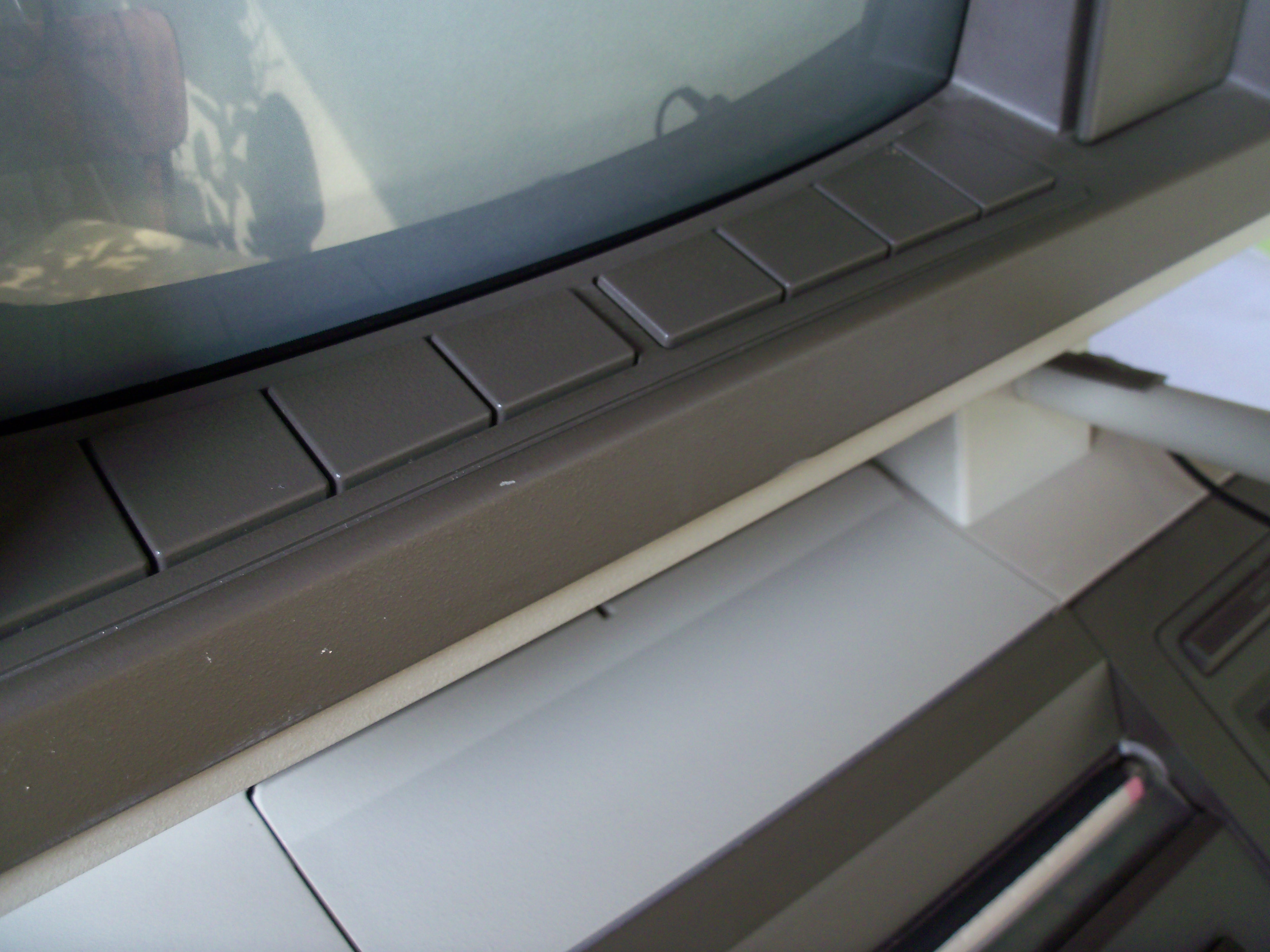 |
Also part of the concept were eight soft keys which were positioned just below the CRT, so that some information on the display could be associated with those keys. This was in general used for menu techniques, where labels at the bottom of the screen matched with each of the keys. On later systems, this menu technique was maintained, however the keys then moved from the display to the keyboard. With its Series 150 PCs, HP introduced a touch screen with light beam technology, which still used the menu concept introduced with the 9845C. |
| The 9845C keyboard layout is exactly the same as that of the other 9845 models. Just the model logo differs. | |
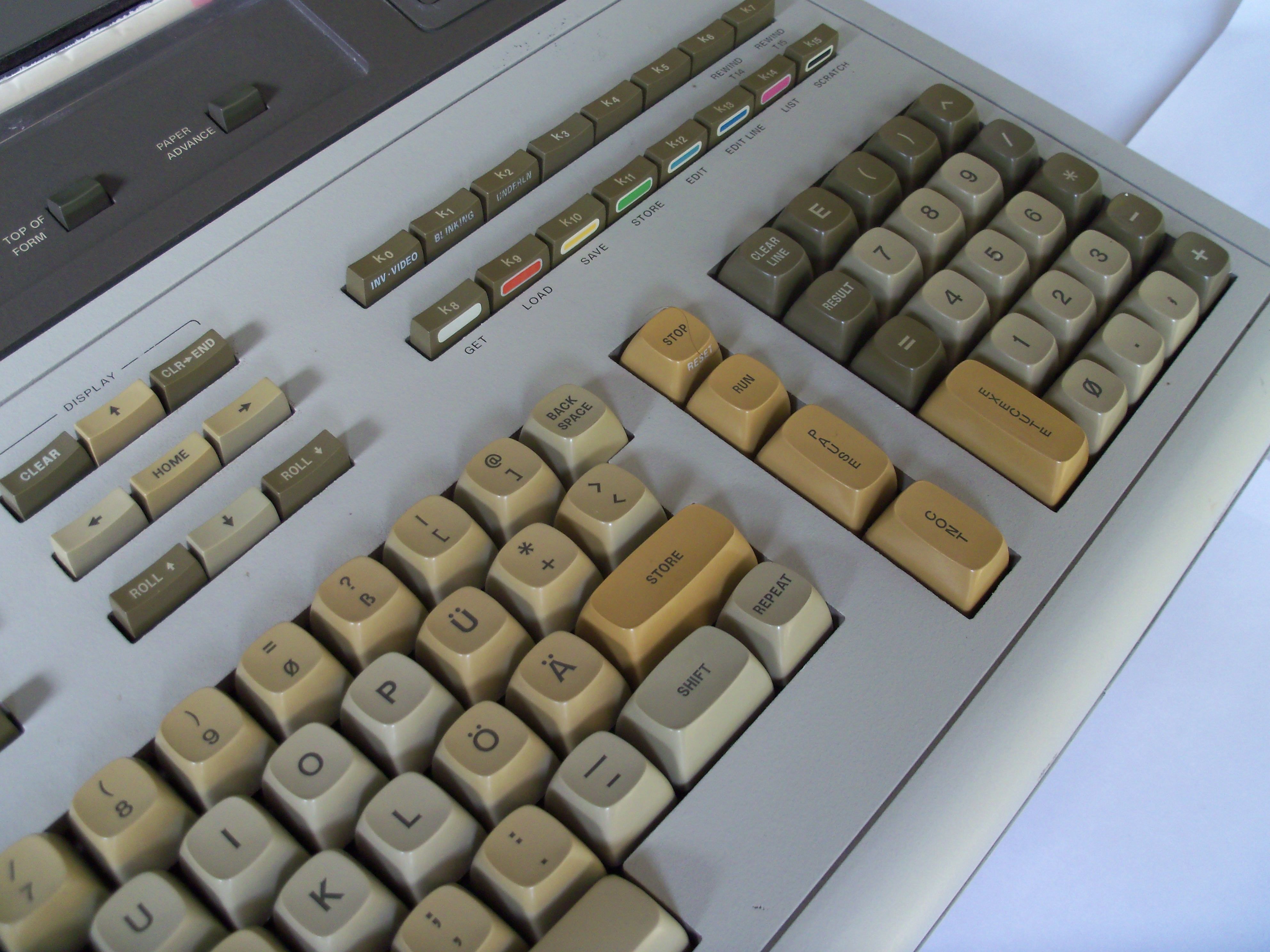 |
Apart from the logo, you can identify a 9845C by the colored function keys, which can be used to easily switch colors while typing. |
 |
Another difference between the 9845B and 9845C are firmware modules. There is a special 9845C graphics option ROM which has to be installed in the left (PPU) ROM drawer. Later this option ROM was superseded by another graphics ROM, which covered both 9845B Model 200 and 9845C graphics. |
 |
There is nothing special in the right (LPU) ROM drawer for the 9845C. |
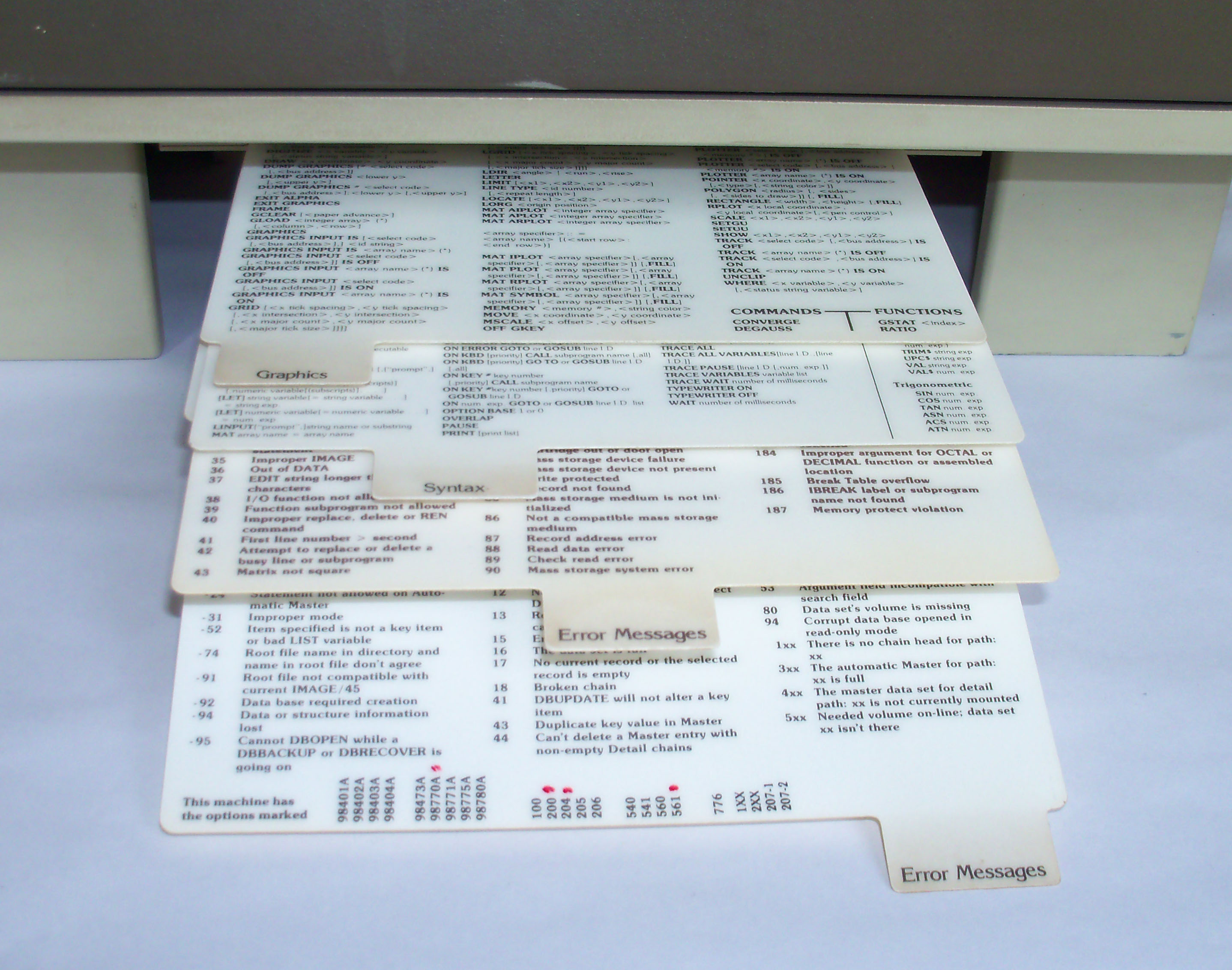 |
The 9845C had its own set of pull-out cards for quick command system configuration and command reference. The pull-out cards are mounted below the display. |
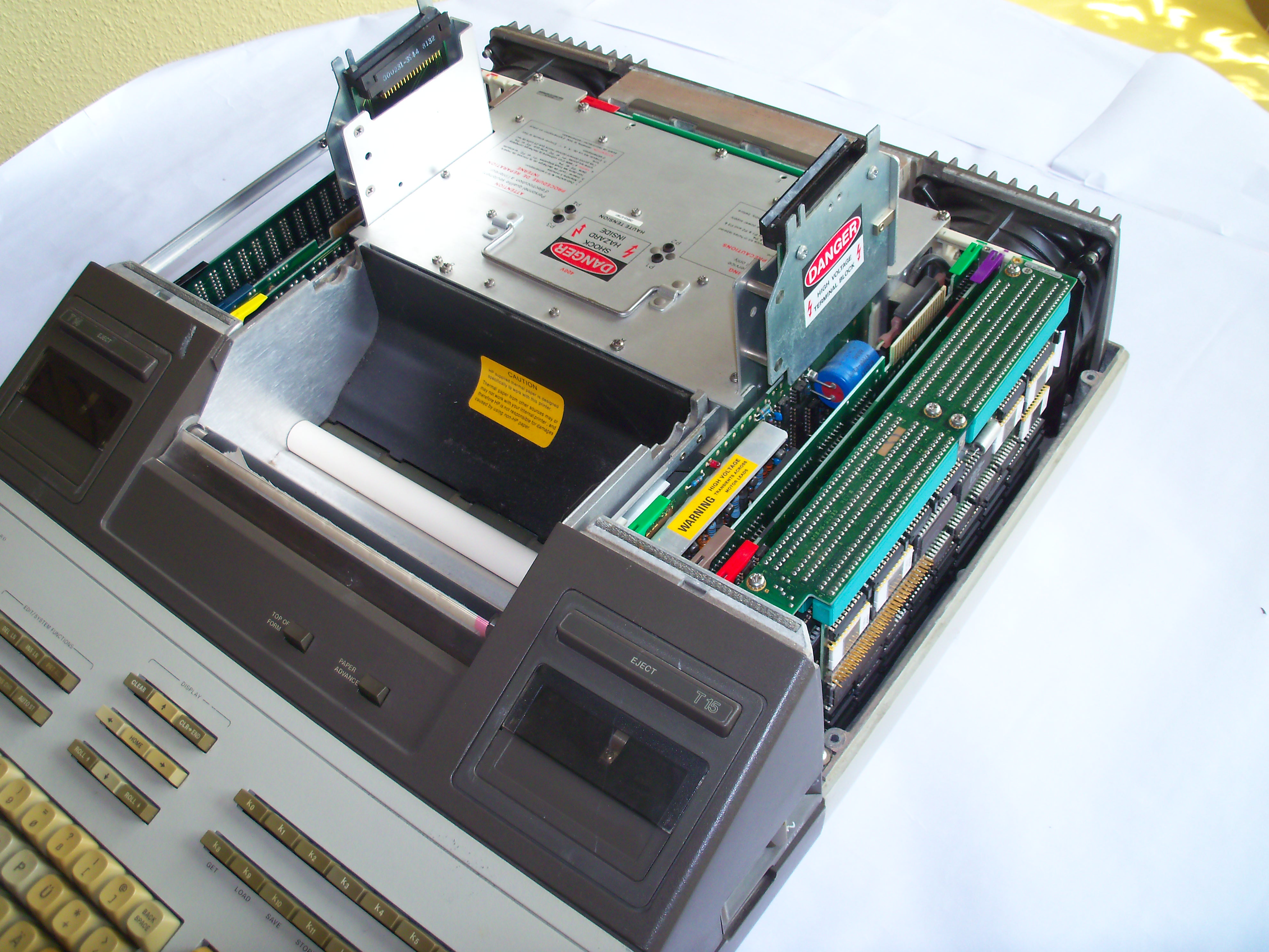 |
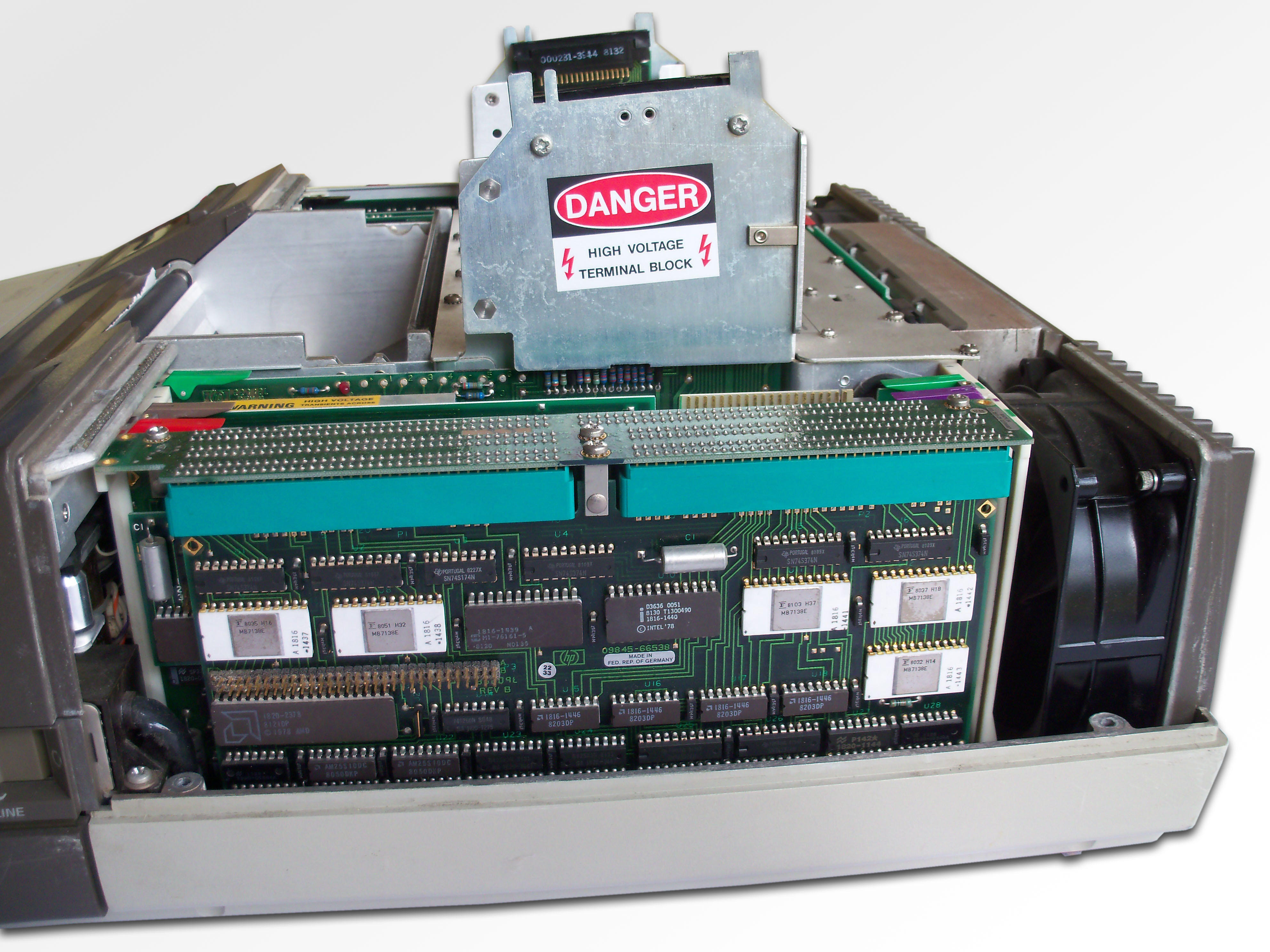
Internally the 9845C mainframe in fact was almost identical to a 9845B mainframe. Internal differences were only by firmware. Almost all 9845C features were in the 98770A display. Both the 9845B and the 9845C could be ordered as standard (Model 100) or enhanced (Model 200) configuration. The Modell 200 included a fast LPU (bitslice processor), a more capable power supply unit and more powerful fans. Here the 9845C Model 200 is shown. From right to left: Fast LPU assembly, PPU ROM/RAM-board, printer controller and printer driver board, and display interconnect board (IO bus for graphics data). |
 |
Close up on the fast LPU. As you cam see, the fast LPU consists of a three board assembly interconnected by a fourth board (called "father board"). The fast LPU was implemented as a large word processor, which again was built up by four 4-bit AMD slice processors (can be seen on the PCB in the front), with one sequencer. The speed gain was achieved not by a higher CPU clock or more efficient architecture (the bit slice processor in fact 'emulated' the original hybrid CPU), but by implementing time critical parts of the BASIC language interpreter in microcode. |
 |
The Model 200 PSU differs from the Model 100 PSU in that it was higher rated, lacked any external test points, but provided a power-good check circuit with LED indicators. |
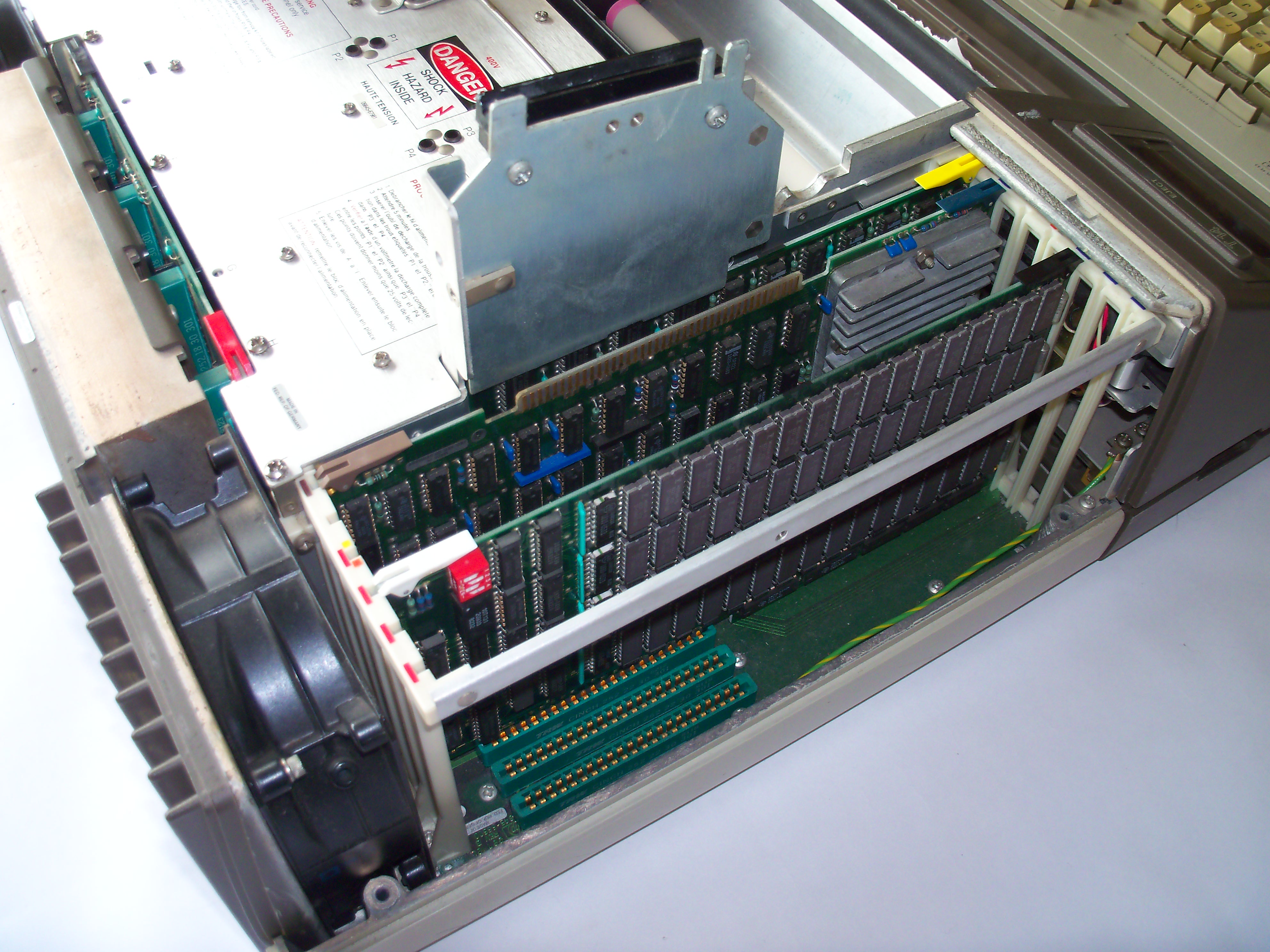 |
The left board cage includes (from up to down): The display interconnect assembly (alpha data interface), the LPU RAM/ROM board, the PPU with its heat sink and a single 512k RAM board (the 9845 could hold up to three of those for max. 1.5 MB RAM). |
More Information
Basic sales information about the 9845C can be found in the 9845C brochure from January 1980. The 9845C was introduced in the December 1980 issue of the HP Journal. Most internal information about the 9845C mainframe is identical to that of the 9845B and can be derived from the installation and operation manuals, the 9845B/C service manual and the CE handbook. The most important source for technical backgrounds are the December 1980 HP Journal, the 98770A service manual, the 98770A CE handbook and the US patent no. 4367465 for the light-pen. See the Documents section for further details.